Company Introduction
Founded in 1947, Resitoflex has been a pioneer of several world class technologies and introduced the same in India in the following Chronologicalmanner:
Seismic Restraint Systems
When it comes to earthquake preparedness, the devil is in the details. Seismic experts say most of the damage from earthquakes is caused not by crumbling walls or collapsing roofs but failures in the less visible, often overlooked, parts of a building—especially pressure piping and other components which if not properly detailed, they risk potentially devastating financial effects from property loss or system shut-downs.”
RESISTOFLEX offers three types of Restraint Systems
Seismic Sway Braces
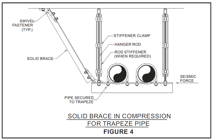
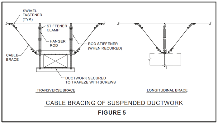
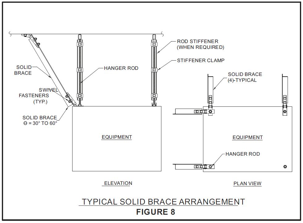
Sway braces are the most important efficient means of keeping suspended equipment, electrical conduits, piping, and duct work in place and to keep them from swaying during earthquakes or bomb blasts. Seismic braces can be flexible using aircraft quality cables, or rigid (solid) using steel sections such as pipe, angles, or strut channels. Braces are typically installed 10-13 m apart, at system turns and at the end of runs. Braces are attached to the pipe/duct at horizontal supports such as clevis's or trapezes. The other end is attached to structure such as overhead concrete slabs or structural steel. Suspended equipment requires a minimum of four braces, one at each corner.
Pressure Piping Systems
Pressure piping systems carry a wide range of fluids and gases around buildings, generally at pressures greater than 1 bar. Systems are usually configured in some combination of horizontal and vertical runs of pipe suspended overhead or mounted on (and penetrating through) walls, floors or roofs.
Seismic Risks
Flexible connections are often required at fixed equipment or where piping crosses an expansion joint or seismic separation.Virtually all of these traits comewith their own seismic risks.
Improperly supported or unbraced piping can fall or sway into adjacent equipment or structures. Joints, connections to equipment, bends, and penetrations are often the source of breaks and leakage, damaging both the piping system and adjacent equipments.
Another common cause of damage, especially in large industrial complexes, is differential movement between points of attachment. Often, pipelines will span two or more connected buildings that may react differently in a quake. Seismic restraints at the interface of the two buildings should take into account the structural aspects of each building.
Longitudinal Bracing
Longitudinal pipe bracing requires the use of a pipe clamp, riser clamp, welded lug, or other hardware that positively attaches to the pipe to prevent slippage. Friction connections such as U-bolts are no-no's for longitudinal restraint because they are highly prone to slips
APPLICATIONS
Mechanical Systems
Electrical Systems
Plumbing Systems
Fire Protection Systems
Pipe, Cable Trays, Bus Ducts & Conduit Bracing Details
Cable Bracing

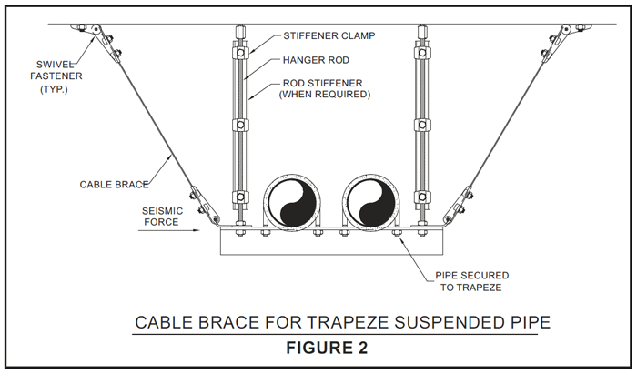
Rigid Or Solid Bracing

Duct Bracing Details
Cable Bracing
Rigid or Solid Bracing
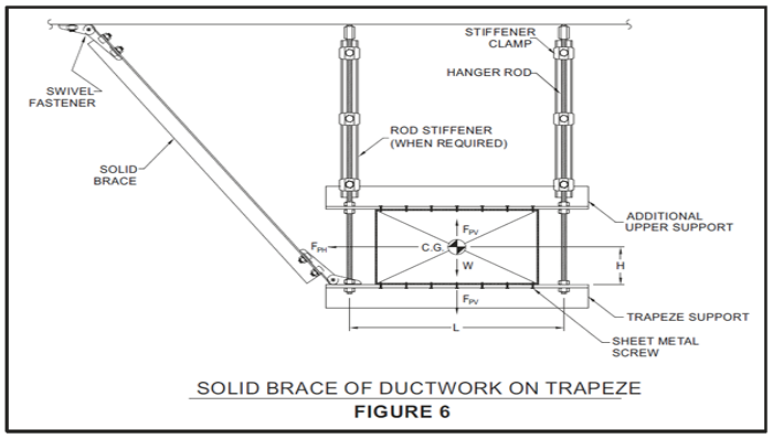
Suspended Equipment Bracing

Pipe Risers
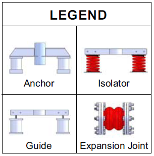
Anchors (PRA) / Guides PRG

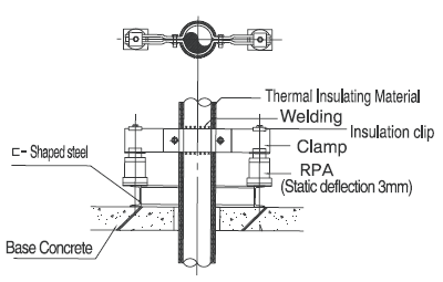
Pipe riser for pressure piping are vertical runs of pressurized piping such as those used in multistory building. Risers are typically supported by a combination of wallmounted supports and additional floor-mounted or roof-mounted supports at the locations of penetrations. Seismic restraints have to designed to accommodate the anticipated inter story drift and the thermalmovement.
Resistoflex Pipe risers are designed to accommodate inter-story drift between adjacent floors, that is, different floors of the building. During an earthquake the supports to fail or the pipe joints to fail and leak , pipe to be dislodged and fall and unbraced riser ti sway and impact adjacent items.
CAUTION - Pipe are vulnerable at penetrations thus floor and roof penetrations are sufficiently oversized to prevent impact. Unrestrained movement of pipes at penetrations may damage the piping and pipe restraints but may also damage flooring, ceiling, partitions, insulation, fire-proofing or other architectural finishes. For insulated risers, the piping insulationmay also be damaged if the pipe chafes at the restraint. If risers are mounted to lightweight partitions, the partitions may be damaged unless they have been designed and braced to resist the piping loads.
Features
Isolated pipe riser anchor incorporating single/multiple spring or rubber material are strategically placed to support the riser and allow expansion & contraction with small and easily calculable load changes. The Spring support systems can be designed to utilize a central isolated anchor which remains neutral during operation, or a totally free-floating system with spring support only. If a single anchor is used, it is located as close as possible to the middle of the riser to direct the pipe to expand away or contract towards the anchor point. By locating the anchor in the center of the riser the expansion and contraction at each end is cut in half. The anchor is designed to withstand the "worst case" forces generated when the water weight is removed for maintenance of equipment without the need to access and re-adjust the mountings. As the number and location of isolators may vary from one set on every floor for maximum load distribution or they may be spaced at greater intervals. Isolated pipe guides should be used in most systems to maintain alignment of anchored or unanchored spring support systems. Risers can be butt welded when installed to assure integrity. They are easy to install and require no maintenance.
Design Condition:
Anchors and Guides are designed to eliminate or limit pipe movement and must be rigidly attached to the structure for effective isolation. Anchors & guides are remote from the piping itself as it is used under the ends of riser clamp and guide ring. Anchors and Guides are manufactured for all pipe sizes.

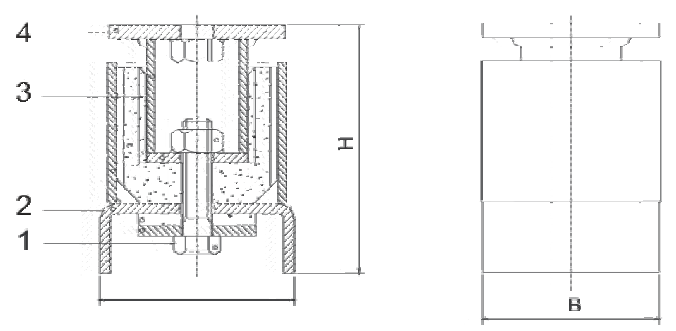
Pipe Anchor & Guide
An all directional Anchor for providing high frequency noise and vibration isolation for all locations where movement of pipe is to be restrained.
Acoustical Neoprene Rubber element is sandwiched between concentric inner steel sleeve with heavy square flange (with or without tapped hole) and outer steel sleeve with channel shaped base which can either be welded to an additional base-plate or welded directly to structural supporting member.

Anchors are always used in pairs.
Note: Base Plate is optional
| S.No. | Item | Material |
|---|---|---|
| 1 | Connection Bolt | Steel |
| 2 | Lower Housing | Steel |
| 3 | Resilient Element | Rubber |
| 4 | Upper Housing | Steel |
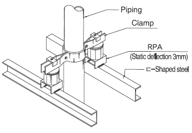
Mode Of Installation


Seismic Snubbers
For Floor Supported Equipments
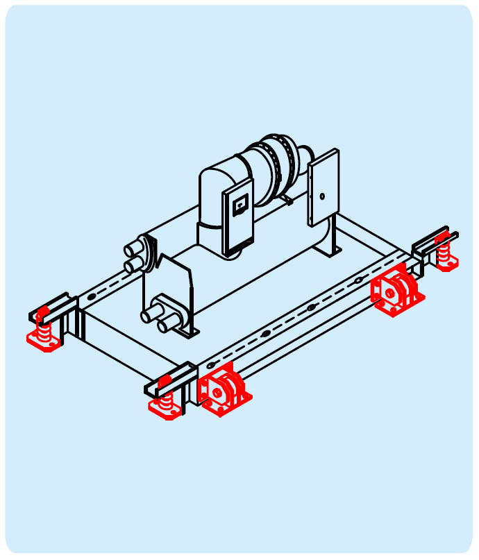

Earthquake is not just a single jolt but an input of random frequencies at different accelerating levels
Mounted equipments can be completely damaged or even fly – off if not fully protected against earthquake
All directional Seismic Snubber will provide safety in vertical, two horizontal modes as well as in the three rocking modes
Snubbers will also take care of errors in alignment and / orminor shifting
Applications:
Air Handling Units, Air Conditioners, Blowers, Bases, Condensers, Chillers, Cooling Towers, Compressors, Fans, Fan Coil Units, Motors, Packaged Units, Piping, D.G. Sets & other essential service equipments installed on Vibration Isolators inAuditoriums, Buildings,Hotels, Hospital, etc.

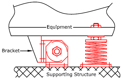
Ssz All - Directional Seismic Snubber
Style SSZ Snubbers are all directional double acting type with interlocking steel members restrained by Neoprene Shock Absorbing Element having physical and non-ageing properties to match the life of the installations. They are structurally very sound.
All contact surfaces are resilient with non-linear stiffness characteristics & are sufficiently thick to allow adequate time for deceleration down to desirable levels.
A special feature of Style SSZ snubber is removable resilient element for checking, if physically damaged accidentally.
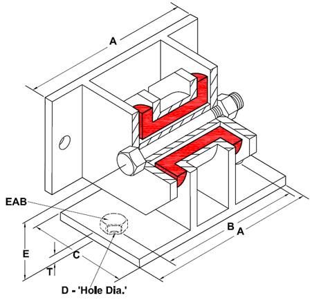

Dimension & Selection Guide By Loads
| CODE | CAPACITY (Kgf) | DIMENSIONS (mm) | RECOMMENDED ANCHOR BOLT 'EAB' (BY OTHERS) ≥Gr. 8.8 | ||||||
|---|---|---|---|---|---|---|---|---|---|
| A | B | C | D | E | F | T | |||
| SSZ2-00220 | 220 | 190 | 158 | 90 | 13 | 76 | - | 6 | M10 |
| SSZ2-00550 | 550 | 210 | 172 | 150 | 15 | 110 | - | 10 | M12 |
| SSZ4-02200 | 2200 | 320 | 254 | 180 | 19 | 127 | 128 | 12 | M16 |
| SSZ4-05500 | 5500 | 370 | 304 | 200 | 27 | 146 | 140 | 20 | M24 |
| SSZ4-11000 | 11000 | 405 | 324 | 280 | 36 | 203 | 210 | 25 | M33 |

India's first Seismic Base Isolated Commercial Building
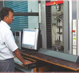
Quasi Static Through Zero Testing

Injection Rubber Moulding
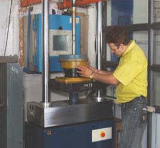
Dynamic Testing With
Servo Pulser
& Climatic Chamber
Unlock Your Potential with Expert Guidance
We’re dedicated to providing
custom-engineered
solutions that enhance efficiency and performance.
Let’s work together to achieve your project goals seamlessly.
